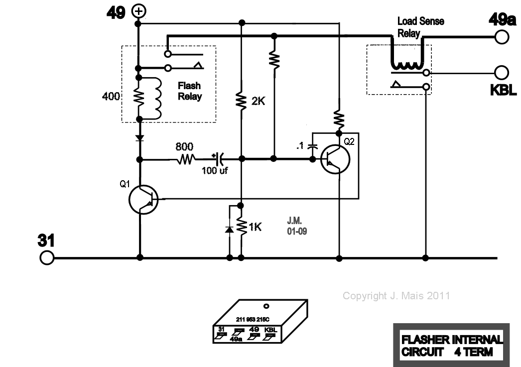
The drawing below shows the electronic circuit inside a typical 4-terminal flasher. Note that there were many variations of this circuit design over the years.
2 transistors. Q1 and Q2, form a multivibrator which drives the Flash relay in the collector circuit of Q1. A small voltage is always present on 49a by way of the 2K resistor (the Load Sense relay has only a few turns of very heavy wire for its coil). When the Turn Indicator signal switch is closed, the turn lamps are connected from Ground to Terminal #49a. Their low resistance drags the voltage at 49a down to nearly zero which, in turn, pulls the base of Q2 lower. Q2 is held in the On state by the 2K resistor when the Turn Indicator is idle. The lowered base drive now allows Q2 to begin turning Off. As it does, the base of Q1 is driven On, energizing the relay and causing the Turn Signals to immediately light.
The 2K resistor is now pulled up to the full 12V level which increases the base drive available to Q2. However, the 100 uf timing capacitor doesn't permit Q2 to turn On immediately. Current continues to flow until the capacitor has charged via the 800 Ohm resistor. At that time, Q2 turns On and allows Q1 to drop out the relay, turning off the lamps. This cycle repeats, with the capacitor charging and discharging.
The dash/speedo signal lamp for the Indicators is connected from +12V to Terminal KBL. Current flow from the Turn Indicator bulbs closes the relay contacts and lights the dash signal. This is why the dash signal flashes in time with the Turn Indicators.
The Load Sense relay "measures" the lamp current. If one lamp burns out, the relay will not close its contacts, and the dash/speedo signal bulb which is connected to KBL will not light, alerting the driver to a burned out bulb.

